
Engineering Tips: Understanding Longitudinal Load Path
An important part of any building is the longitudinal bracing system. Our engineers’ goal is to design this system to follow the safety standards per the applicable codes while using as efficient a system as possible. This system provides a load path for both seismic and wind loads to safely travel through the building and into the ground. Longitudinal loads are created by both seismic and wind loads, though only one usually governs the design. A building does not have to be designed for a hurricane and an earthquake at the same time.
Earthquakes create longitudinal seismic loads by moving a building’s foundation (See Figure 1).
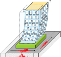
Seismic loads relate directly to the mass of a structure, which includes dead load and collateral load. As the ground shakes, the foundations move with the ground, but the structure remains in place. This is similar to accelerating or braking in the car.
For wind loads, the wind pushes and pulls the wall panels on the end walls and roof (See Figure 2).
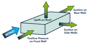
The panels distribute wind load to the girts. The girts transfer the loads into the endwall columns. Those columns send half of the load to go to the floor and half of the load to the rafter of the end frame. The rafter distributes the load to the roof struts. If the loads are low enough, the purlins may serve as roof struts, but larger loads require additional members to transfer them. When wind reaches the roof braced bay, the load travels along the strut and into the rod. (See Figure 3).
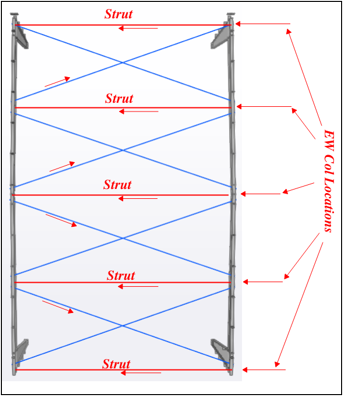
An important thing to note is that rods only work in tension as they do not have much strength in compression (a rod used in place of a column would support no load). Because of this, the loading must travel through the strut first before it can pull on the rod. This is why the loads must go through struts before they engage the roof rod bracing.
Through this network of rods and struts the load eventually reaches the eaves of the building. In some cases, with higher loads or larger bays, our engineers may add additional strut members to resist these loads. The load travels through the eave until it reaches a wall braced bay (either portal frames or rod bracing). Once it reaches a braced bay, the load travels into the wall bracing system and down into the ground.
Several items can greatly affect the longitudinal bracing system:
- Parapets (wind increases significantly with presence of parapets)
- Masonry or other hardwalls (more seismic weight to resist)
- Mezzanines or cranes (more seismic weight to resist)
- High collateral loads (more seismic weight to resist)
- RTUs or hanging loads from roof (more seismic weight to resist and wind may increase significantly)
As with other building elements, every design involves tradeoffs. For example, increasing the number of sidewall bracing bays may allow engineers to use smaller portal frames with more clearance. To make sure our design team can produce the most efficient building, it is important for builders and engineers to work together. Builders should report the loads in Box 3 of the sales order as accurately as possible as well as other loads such as RTUs and extra collateral. Changing this information after design has begun can lead to drastic changes in the building design. This information will determine not only what will govern the design, but how sturdy the longitudinal bracing system needs to be.